Collections


New Products
-
eXtremeRate Replacement Full Set Shell with Buttons for Steam Deck OLED - Gradient Translucent Bluebell
Regular price $46.99Regular priceUnit price per -
eXtremeRate Replacement DIY Rear Back Plate for Nintendo Switch 2 Handheld Console (Without Kickstand) - The Great Wave
Regular price $25.99Regular priceUnit price per -
eXtremeRate D-Pad Version Replacement Full Set Shells with Buttons for Nintendo Switch 2 - Deluxe Version - White
Regular price $33.99Regular priceUnit price per -
eXtremeRate DIY Replacement Full Set Buttons for Nintendo Switch 2 - Black
Regular price $18.99Regular priceUnit price per -
eXtremeRate Replacement FPC cables for eXtremeRate Multi-Colors Luminated Buttons DTF V2 LED Kit, Compatible with Xbox Series X & S Controller
Regular price $18.99Regular priceUnit price per -
eXtremeRate D-Pad Version Replacement Full Set Shell Case with Buttons for Joycon 2 of Nintendo Switch 2 - Essence Version - Wood Grain
Regular price $23.99Regular priceUnit price per -
eXtremeRate Replacement Full Set Shells with ABXY Buttons & Screen Protector for Nintendo Switch Lite - Sky Blue
Regular price $26.99Regular priceUnit price per$0.00Sale price $26.99Vendor:eXtremeRateSold out -
eXtremeRate Replacement Thumbsticks with Original Touch Sensing for Steam Deck LCD & OLED - Orange & Black
Regular price $9.99Regular priceUnit price per -
eXtremeRate Replacement Thumbsticks with Original Touch Sensing for Steam Deck LCD & OLED - New Hope Gray
Regular price $9.99Regular priceUnit price per -
eXtremeRate Replacement Thumbsticks with Original Touch Sensing for Steam Deck LCD & OLED - Cherry Blossoms Pink
Regular price $9.99Regular priceUnit price per -
eXtremeRate Replacement Thumbsticks with Original Touch Sensing for Steam Deck LCD & OLED - Black
Regular price $9.99Regular priceUnit price per -
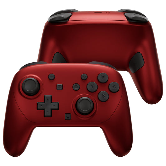
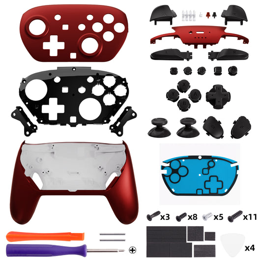
eXtremeRate DIY Replacement Full Set Shells with Buttons for Nintendo Switch 2 Pro Controller - Scarlet Red
Regular price $29.99Regular priceUnit price per -
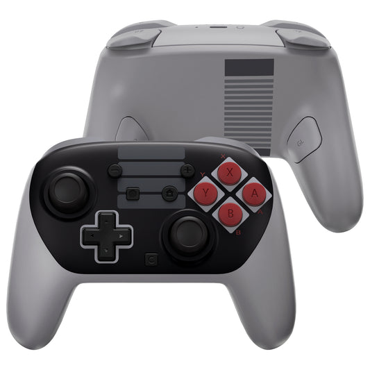
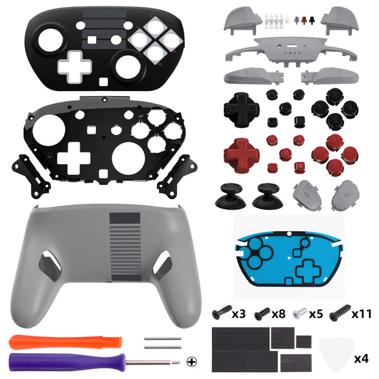
eXtremeRate DIY Replacement Full Set Shells with Buttons for Nintendo Switch 2 Pro Controller - Classic NES Style
Regular price $28.99Regular priceUnit price per -
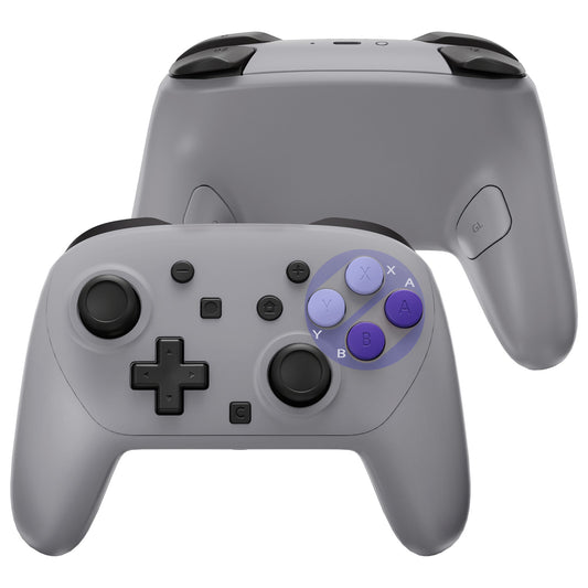
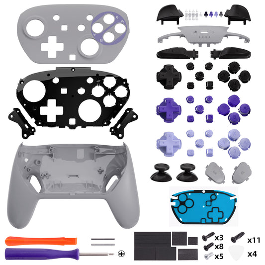
eXtremeRate DIY Replacement Full Set Shells with Buttons for Nintendo Switch 2 Pro Controller - Classic SNES Style
Regular price $28.99Regular priceUnit price per -
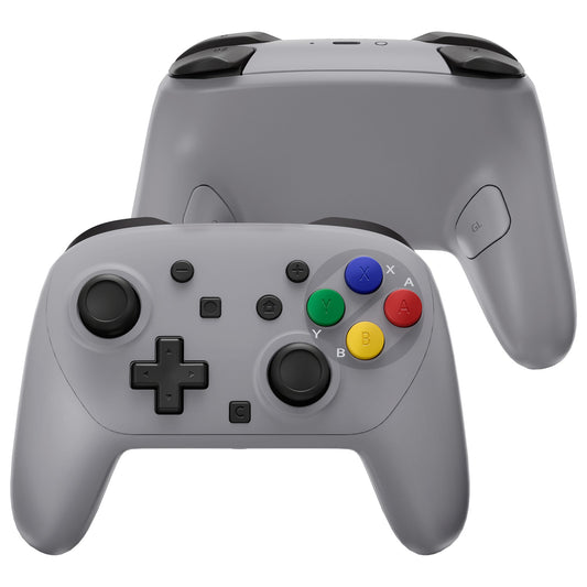
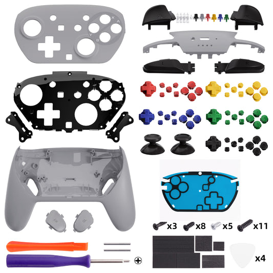
eXtremeRate DIY Replacement Full Set Shells with Buttons for Nintendo Switch 2 Pro Controller - SFC SNES Classic EU
Regular price $28.99Regular priceUnit price per